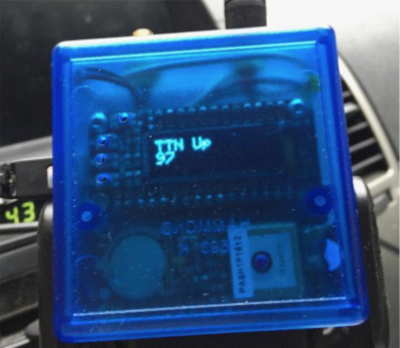
The ManhattanMapper is a custom built mapping device used to measure network coverage from a car driving around New York City. It was constructed using Adafruit Feather boards with software written for the Arduino framework. The following describes the process of building the device and discusses the hardware and software involved.
Shortcuts / User Scenario / Hardware / Software / Next Steps
The Things Network New York is one of 600 communities around the world collaborating to build a free and open LoRaWAN network that is owned and operated by its users. The first city covered by TTN was Amsterdam - it took 10 gateways to establish complete network coverage. With a city as large, dense, and tall as New York, it will take a few hundred gateways. How many will it take, exactly? We don’t know. Therefore, the process is going to be iterative - we deploy some gateways, measure the coverage, plan how to most efficiently fill in the gaps, and repeat.
Right now (June 2018) there are fewer than 20 gateways deployed around the city, many without rooftop antennas. Any new gateway not immediately next to an existing one will expand the coverage significantly.
The basic idea is that the user of the ManhattanMapper will put the device in a car that regularly travels around New York City. The device is plugged in to a USB port for power, but has a small rechargeable battery which can power it for a few hours or more if necessary.
There is no need to interact with the device during normal operation. It simply locates itself in space via GPS and transmits a packet of bytes encoded with that location periodically to The Things Network. When the location packet arrives at the server, we know there is network coverage in that location.
The device has a display and four buttons as well as a number of LED’s that comprise its user interface. The display shows a splash screen on startup and status information as directed by the buttons.
The basic hardware is an assembly of 4 feather form-factor boards from Adafruit:
Additional hardware includes
The original sketch had the boards organized thusly:
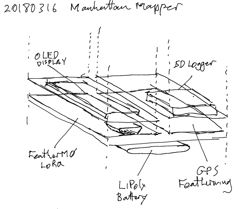
I ended up moving the GPS to be on top of the datalogger because I wanted the GPS’ built-in antenna to abut the top of the enclosure, exposing it to the sky (albeit through plastic). Also, a battery cannot fit between the board assembly and the bottom of the enclosure. I used a much smaller battery and it fits nicely on its side next to the boards.
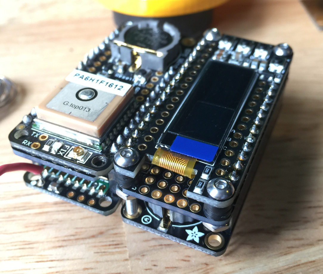
The boards communicate thusly:
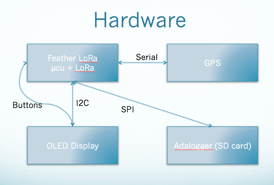
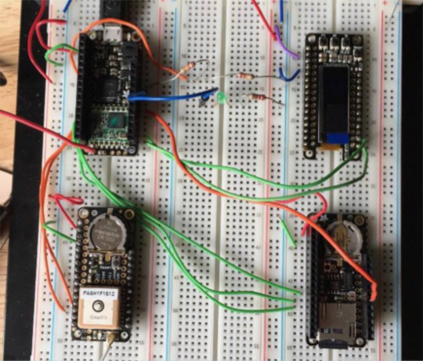
Here they are breadboarded (clockwise from upper left: Feather LoRa, OLED, Adalogger, GPS):
I put the hardware together tentatively, with some fear about soldering things together wrong and having to either do a lot of solder rework or buy new boards. I employed a strategy of soldering pins to the doubler only when I needed to (or when further assembly was going to prohibit access to the pin). The filled in symbols on the sketch below indicate soldered pins.
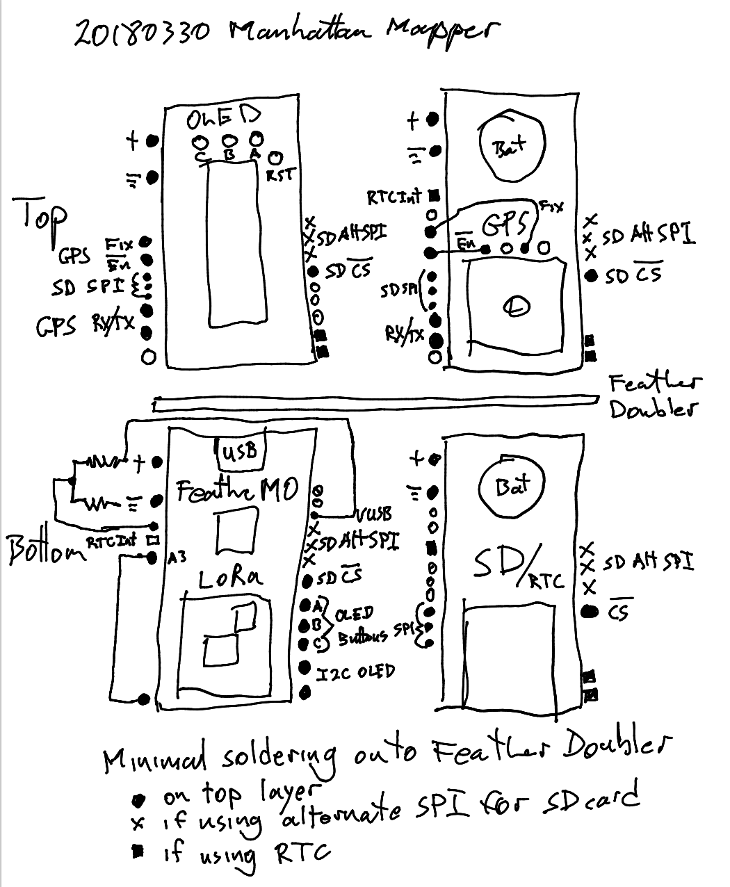
All signal lines go from the µCU board to one of the three FeatherWings. There are no signals between the daughterboards. By the nature of the assembly, any signals going to the OLED board need not be soldered to the doubler board, because the signals are conveyed directly by pins in headers. Any pin conveying a signal to either the GPS or Adalogger needed to be soldered both to the OLED board and the GPS board (the top boards have the pins for soldering). Signals to the Adalogger travel up the header from the µCU, into the OLED pin, into the doubler crossover, into the GPS pin, and finally down the header into the Adalogger.
I purchased 3 different cases from Hammond, because I wasn’t sure which would fit the assembly. It turned out that the smallest one worked. In fact, once I cut the corners off of the four feather boards and notches out of the doubler, the assembly fit snugly without further attachment.
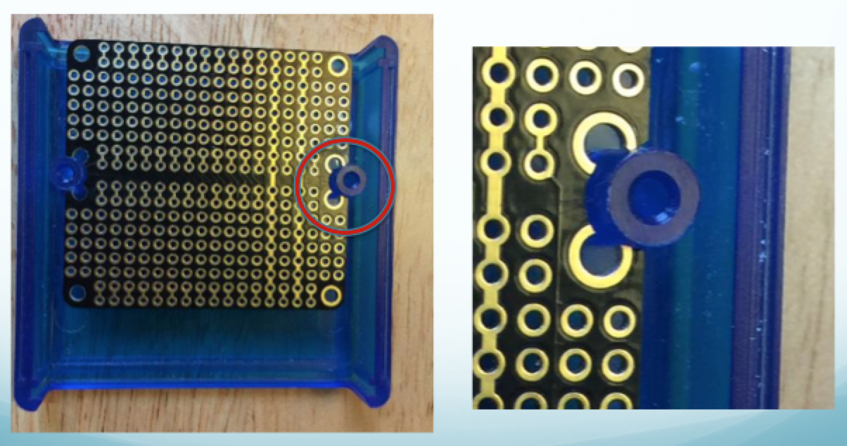
One of the physical challenges was getting the top of the OLED screen to be at the same height as the top of the GPS module. It was important that the screen be close to the inner surface of the enclosure, because the blue plastic is not perfectly transparent and further away the screen would be too blurry to read.
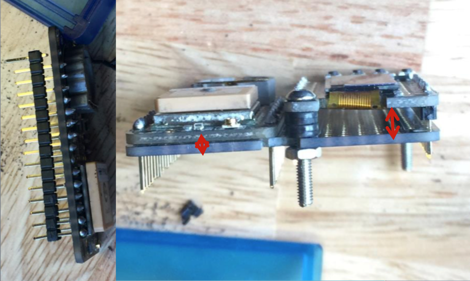
The first thing I did was remove the plastic spacer from the male headers on the bottom of the GPS board. That allows that board to sit right up against the doubler board. I made sure to put a piece of electrical tape down between the two to prevent any spurious electrical connections. Next I made sure to leave extra space when I soldered the OLED board to the doubler, ensuring that it would match the height of the GPS.
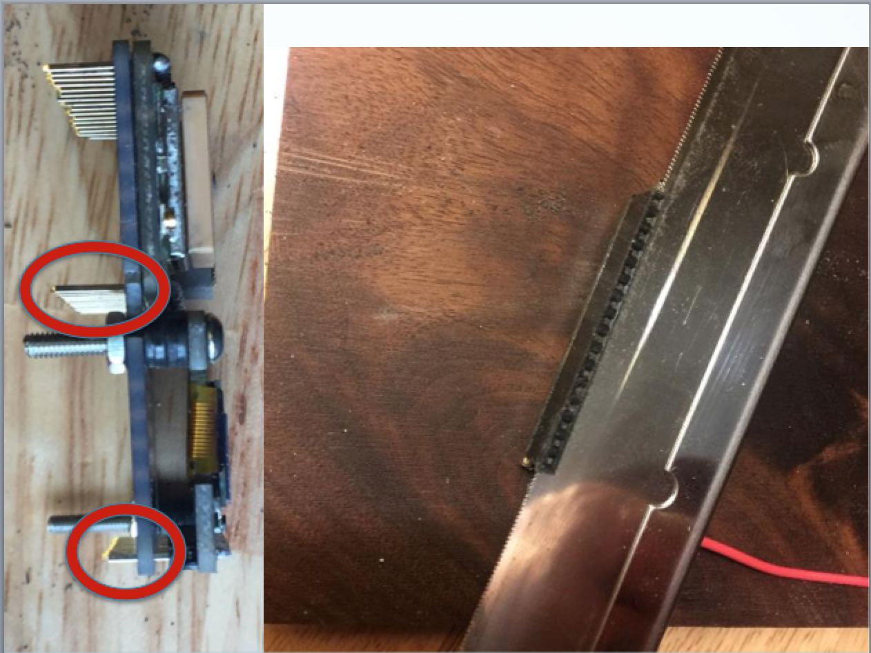
Unfortunately, the raised OLED board meant the pins on the other side that need to mate with the µCU headers were too short. Note the difference in pin lengths circled in red in the image above. As I worked on fitting the whole thing in the enclosure I experienced a few episodes of unreliable operation resulting from the µCU board having slipped off the pins. Thankfully, I was able to solve the problem by using a razor saw to cut the top 1.5mm off the female headers, resulting in a shorter travel to get to the grippy electrical connection below.
A late addition was a USB regulator. The Feather LoRa has no diode on VUSB meaning it is possible for battery current to back up into VUSB. I saw some odd behavior where the unit failed to get USB power after turning my car off. I had a hypothesis that it was related to this and so installed a USB power regulator. It didn’t change the odd behavior, but I feel better knowing it’s in there. Why did I use an SMD part? That’s what I was looking at on Digikey and it seemed like it would fit.
To wire in the regulator I had to cut the trace from the micro-USB connector to VUSB. Now where to pick off that incoming 5v? I removed the USB-power LED and got myself a nice little pad. I feed the output of the regulator onto the Feather-standard VUSB pin.
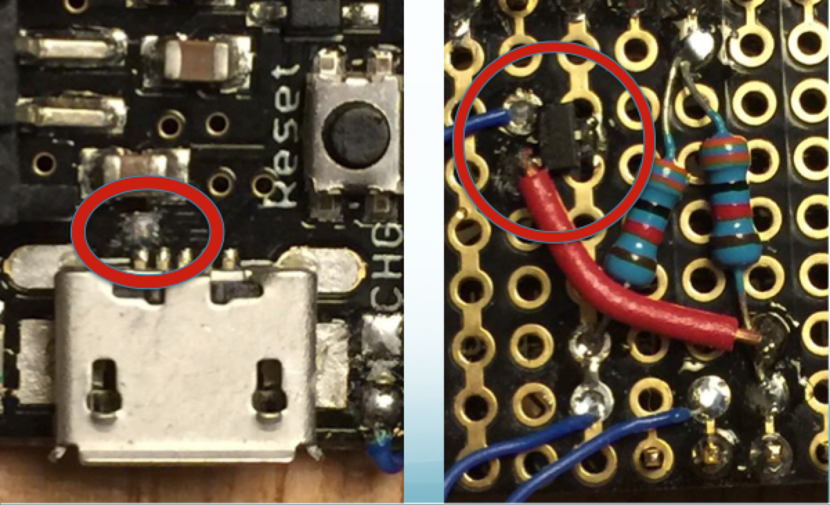
(The pair of resistors is a divider from VBAT feeding into an analog input pin for battery level testing.)
The final modification was the addition of 3D printed buttons over the SMD buttons on the Feather OLED board. In the first build I had to press the buttons using a toothpick, which was inconvenient. The wide diameter base of the buttons sit directly on the SMD buttons. The narrower tops of the buttons poke through beveled holes in the enclosure.
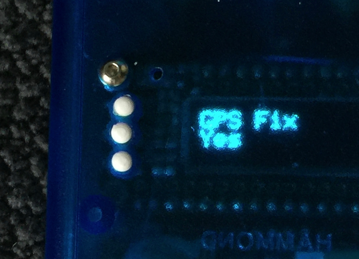
In order to keep the buttons exactly spaced between the board and enclosure, I had to mount the four-feather assembly to the enclosure. You can see one of the four hex bolts in the picture right above the white buttons.
The Manhattan Mapper is an Arduino sketch that relies on a stack of libraries to do all the detailed work.
| ||||
|
|
|
|
|
|
|
|||
|
|
|||
The top level code is at https://github.com/frankleonrose/ManhattanMapper.
The project has a platformio.ini file that specifies all dependencies as well as build flags. Running platformio run will download all packages into a project-local subdirectory and build the project. I highly recommend installing PlatformIO and using it. No need to integrate it with your editor, but you can if you like. Of course it is possible to build the project using the Arduino IDE as well. You’ll have to hunt for the repos using the GUI. I leave that as an unpleasant exercise for the reader.
After setup, the primary loop is concise because it relies on subsystems to take care of themselves. It looks like this:
void loop() {
  lorawan.loop();
  uiLoop();
  if (!ModeSend.isActive(gState) && !ModeAttemptJoin.isActive(gState)) {
    // Do parsing and timer optional things that could throw off LoRa timing
    // only while NOT sending.
    gTimer.update();
    gpsLoop(Serial);
    gState.setGpsFix(gpsHasFix()); // Quick if value didn't change
  }
  gRespire.loop();
}
The basic application state is represented by a single struct that holds the variables that change as the device moves through space and time and a user operates on it. You can see a reference to gState in the loop() code above.
bool _usbPower;
float _batteryVolts;
bool _gpsFix;

GpsSample _gpsSample;
uint32_t _gpsSampleExpiry;

uint32_t _ttnFrameCounter;
uint32_t _ttnLastSend;
bool _joined = false;

// Display states
uint8_t _page = 0;
uint8_t _field = 0;
bool _buttonPage = false;
bool _buttonField = false;
bool _buttonChange = false;
bool _redisplayRequested = false; // Toggle this to trigger redisplay.
The behavior of the application is specified by a hierarchy of Respire “Modes” defined in mm_state.cpp. The Modes activate and deactivate based on changes in application state, the passage of time, and the activation of parent and child modes.
The Respire framework simplifies application development by clearly separating concerns.